
mooring systems
An offshore mooring system consists basically out of three parts. An anchor system, a mooring line and a specific mooring layout. The mooring system layout depends on the local environmental conditions and the purpose of the offshore unit. The most important six mooring layout types are elaborated below.
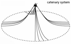
Catenary mooring system
A catenary mooring system is the most common mooring system in shallow waters. Through gravity the catenaries, between the floating unit and the seabed, will show the typical shape of a free hanging line. The catenaries are hanging horizontally at the seabed. Consequently the catenary lengths have to be larger than the water depth and the anchor points in a catenary mooring system are subjected to horizontal forces. The catenary configuration provides a restoring force on ship motions mostly through the weight of the catenaries.
A catenary mooring system is the most common mooring system in shallow waters. Through gravity the catenaries, between the floating unit and the seabed, will show the typical shape of a free hanging line. The catenaries are hanging horizontally at the seabed. Consequently the catenary lengths have to be larger than the water depth and the anchor points in a catenary mooring system are subjected to horizontal forces. The catenary configuration provides a restoring force on ship motions mostly through the weight of the catenaries.
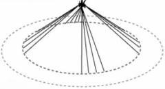
Taut leg mooring system
In a taut leg mooring system the pre-tensioned mooring lines arrive under an angel at the seabed. Typically the angle between the line and the seabed is between 30 and 40 degrees. The anchor points in a taut leg mooring system have to be capable of withstanding horizontal and vertical forces. In a taut leg mooring, the restoring forces are generated by the elasticity of the mooring line.
In a taut leg mooring system the pre-tensioned mooring lines arrive under an angel at the seabed. Typically the angle between the line and the seabed is between 30 and 40 degrees. The anchor points in a taut leg mooring system have to be capable of withstanding horizontal and vertical forces. In a taut leg mooring, the restoring forces are generated by the elasticity of the mooring line.
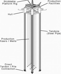
Tension Leg (TL) mooring system
As the name ‘tension leg’ mooring system suggest does the system consist of tubular steel legs. The legs consist of multiple tubular steel members which are called tendons. Tensioning the steel legs is done by buoyancy in the floating offshore unit. The high tension in the tension legs limits horizontal offsets to a small percentage of the water depth. Due to the high axial stiffness in the tendons the heave, roll and pitch motions are negligible.
As the name ‘tension leg’ mooring system suggest does the system consist of tubular steel legs. The legs consist of multiple tubular steel members which are called tendons. Tensioning the steel legs is done by buoyancy in the floating offshore unit. The high tension in the tension legs limits horizontal offsets to a small percentage of the water depth. Due to the high axial stiffness in the tendons the heave, roll and pitch motions are negligible.
Single point mooring systems
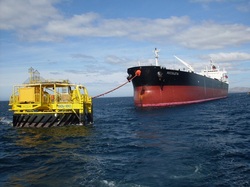
Buoy System
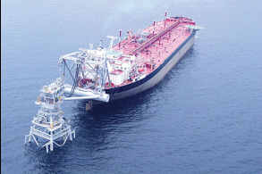
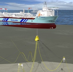
A single point moored buoy system consists of a permanently moored buoy. The buoy has a bearing system that allows a part of it to rotate around the moored geostatic part. When the offshore unit is connected to the buoy it will be able to rotate itself into the dominant environment. Consequently the system will minimise the loads on the mooring system of the buoy. The mooring system can also be combined with a fluid transfer system that enables connection of (subsea) pipelines to the offshore unit. The buoy and the offshore unit can be connected in different manners. Most common are hawser, rigid arm or soft yoke.
Buoy System
A single point moored buoy system consists of a permanently moored buoy. The buoy has a bearing system that allows a part of it to rotate around the moored geostatic part. When the offshore unit is connected to the buoy it will be able to rotate itself into the dominant environment. Consequently the system will minimise the loads on the mooring system of the buoy. The mooring system can also be combined with a fluid transfer system that enables connection of (subsea) pipelines to the offshore unit. The buoy and the offshore unit can be connected in different manners. Most common are hawser, rigid arm or soft yoke.
Tower System
The single point tower mooring system consists of a tower structure that is permanently fixed to the seabed by means of piles or a gravity base. The tower contains a bearing system that allows a part of it to rotate around the fixed geostatic part. When moored to this rotating part of the tower with a mooring connection, the offshore unit is able to rotate around the geostatic part of the tower. The tower system can also be combined with a fluid transfer system that enables connection of (subsea) pipelines to the offshore unit. Water depth and specific environmental conditions are dominant design factors. The mooring connections between the tower and offshore unit are commonly the following systems: hawser and soft yoke.
The single point tower mooring system consists of a tower structure that is permanently fixed to the seabed by means of piles or a gravity base. The tower contains a bearing system that allows a part of it to rotate around the fixed geostatic part. When moored to this rotating part of the tower with a mooring connection, the offshore unit is able to rotate around the geostatic part of the tower. The tower system can also be combined with a fluid transfer system that enables connection of (subsea) pipelines to the offshore unit. Water depth and specific environmental conditions are dominant design factors. The mooring connections between the tower and offshore unit are commonly the following systems: hawser and soft yoke.
Turret mooring
The single point turret mooring system consists of a turret assembly that is integrated into a vessel and permanently fixed to the seabed by means of a mooring system. The turret system contains a bearing system that allows the vessel to rotate around the fixed geostatic part of the turret, which is attached to the mooring system. The turret mooring system can be combined with a fluid transfer system that enables connection of (subsea) pipelines to the offshore unit like a FPSO. The turret mooring system can be located external and internal on the floating unit.
The disconnectable turret mooring system is often used in an artic environment. If it necessary to disconnect a (subsurface) buoy keeps the mooring lines and risers connected.
Spread mooring system
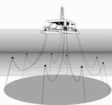
Spread mooring systems are multi-point mooring systems that moor offshore units to the seabed using multiple mooring lines. The offshore unit is positioned in a fixed heading, which is determined by the sea and weather conditions. The symmetrical arrangement of anchors helps to keep the offshore unit on its fixed heading location. The spread mooring system does not allow the vessel to weathervane, which means to rotate in the horizontal plane due to wind, waves or current. Spread mooring is versatile as it can be used in any water depth, on any vessel, in an equally spread pattern or a group.
Spread mooring systems are multi-point mooring systems that moor offshore units to the seabed using multiple mooring lines. The offshore unit is positioned in a fixed heading, which is determined by the sea and weather conditions. The symmetrical arrangement of anchors helps to keep the offshore unit on its fixed heading location. The spread mooring system does not allow the vessel to weathervane, which means to rotate in the horizontal plane due to wind, waves or current. Spread mooring is versatile as it can be used in any water depth, on any vessel, in an equally spread pattern or a group.
Dynamic positioning
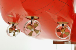
Dynamic positioning does not use mooring lines. Instead a computer controls the vessel's thrusters and propellers to maintain position. Position reference sensors, combined with wind sensors, motion sensors and gyro compasses, provide information to the computer pertaining to the vessel's position and the magnitude and direction of environmental forces affecting its position. DP can be used in combination with other mooring systems to provide additional redundancy.
Dynamic positioning does not use mooring lines. Instead a computer controls the vessel's thrusters and propellers to maintain position. Position reference sensors, combined with wind sensors, motion sensors and gyro compasses, provide information to the computer pertaining to the vessel's position and the magnitude and direction of environmental forces affecting its position. DP can be used in combination with other mooring systems to provide additional redundancy.
Catenary calculations
|
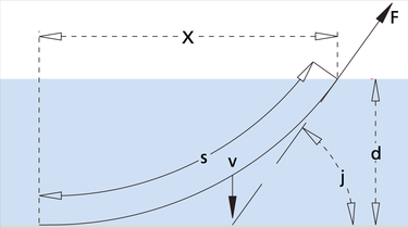
A catenary mooring line will have a part which is laying on the seafloor and a part of the mooring line suspended in the seawater. The part that is uspended in the seawater will take on a catenary shape. Depending on the waterdepth, the weight of the mooring line and the force applied to the mooring line at the fairlead, the length of the suspended mooring line S in [m] can be calculated with:
|
In the Figure above a catenary mooring line is shown. The angle is the angle between the mooring line at the fairlead and the horizontal shown as angle j. The force applied to the mooring line at the fairlead is given as F.
|
|
The waterdepth plus the distance between sealevel and the fairlead in [m] is d in this equation. w is the unit weight of the mooring line in water in [t/m].
The horizontal distance X in [m] between the fairlead and the touchdown point of the mooring line on the seabed can be calculated with:
The weight of the suspended chain V in [t] is given by:
De shape of a catenary mooring line is given by the function:
The shape of the catenary line is uniquely determined by parameter b given by:
<<<<<<<<<<<<<<<<<
PLAY AROUND WITH THE PARAMETERS FOR YOUR OWN MOORING LINE SHAPE <<<<<<<<<<<<<<<<< |
