
OTEC load Case
|
Assumptions:
|
|
Calculations
Windload
Wind profile
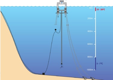
Wind loads caused by a 30 m/s wind at 10 meter above sea level. The wind speed is distributed over the height according to the following formula:
Wind profile
Wind loads caused by a 30 m/s wind at 10 meter above sea level. The wind speed is distributed over the height according to the following formula:
Wind blocks
To include the wind profile, separate wind blocks were assigned according to the height of the area the wind load had an effect on. To each wind block we attached a wind speed multiplication factor to match the wind profile.
To include the wind profile, separate wind blocks were assigned according to the height of the area the wind load had an effect on. To each wind block we attached a wind speed multiplication factor to match the wind profile.
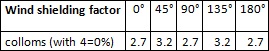
Wind shielding
In some directions parts of the structure are shielded of by other parts. To take this wind shielding into account we applied wind shielding factors. Shielding factors were applied to the columns.
In some directions parts of the structure are shielded of by other parts. To take this wind shielding into account we applied wind shielding factors. Shielding factors were applied to the columns.
Loading areas and coefficients
The semi-submersible was divided in simple blocks which all had a side and front area. In this way the projected wind area could be calculated. The blocks all got a certain shape and height coefficient addressed to them according to the MODU code.
Formula:
The semi-submersible was divided in simple blocks which all had a side and front area. In this way the projected wind area could be calculated. The blocks all got a certain shape and height coefficient addressed to them according to the MODU code.
Formula:
With the following formula the wind loads can be calculated. These wind loads will presumably act on half the height of the different blocks. Because of the shape of the areas this will coincide with the CoG of the blocks.
Since we are in the beginning of the design process we are allowed the simplifications mentioned above. For a more detailed wind loading it’s good to use an accurate scaled model to use in wind tunnel tests.
Since we are in the beginning of the design process we are allowed the simplifications mentioned above. For a more detailed wind loading it’s good to use an accurate scaled model to use in wind tunnel tests.
Current Loads
Slender structure
Although the structure should be classified as a large-volume structure, it may be treated as a slender structure for prediction of current loads. [2]
Morison’s equations
To calculate the loads on slender structures the Morison equation is used. Morison’s equation includes drag forces and inertia forces. Since the current velocity is uniformly distributed, we assume that the current velocity does not change in space and time (no acceleration) and the structure is stationary. So the structure will only experience drag forces and no inertia forces. The formula for the current force becomes:
For the drag coefficient we use the Keulegan-Carpenter number.
After taking various
values for the wave period (Tw = 0 .. 80), the KC value always stays
between the 0 and 6.
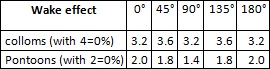
Wake effects
The force on a member downstream of another member is influenced by the wake generated upstream. The current speed is about 0,7 m/s in our case. The distances between the columns and pontoons are around 10 meters. This means that the current has just a little more than 10 seconds to recover its flow. We assume that the wake effect does not play a significant role in this assignment.
The force on a member downstream of another member is influenced by the wake generated upstream. The current speed is about 0,7 m/s in our case. The distances between the columns and pontoons are around 10 meters. This means that the current has just a little more than 10 seconds to recover its flow. We assume that the wake effect does not play a significant role in this assignment.
Drift forces
In order to get an acceptable estimate for the
second order wave forces (wave drift forces), we will use an approximation for
the quadratic transfer function of the vertical cylinders (4 columns and the
seawater pipe). Using the classic definition for the average wave drift force;
and taking the QTF out of the integral (since we
assume it to be approach the high frequency limit) allows us to use simple
Euler integration using the spectra. For the five vertical cylinders, the HFL
of the is (where ‘r’ is the radius of the cylinders under considerations);
